This document reflects the v6.2.3 version of the source code.
|
The User Guide explains how to install and use the DAQ40 software, refer to the Developer Guide to learn how to build and modify the source code. Both guides concern only the software, for the firmware please refer to the Firmware Guides. For the Experiment Control System components and software (implemented on top of the DAQ40 software) please refer to https://lhcb-ecs.web.cern.ch/.
Setup
The DAQ40 software packages provide base functionalities for both AMC40 and PCIe40 setups. They are required before you can successfully install several other packages, including for example:
-
gbtserv -
lhcb-pcie40lli -
lhcb-pcie40lli-devices -
DQMP
DAQ40 software releases are now managed by a GitLab Continuous Integration pipeline. This allows new features and bug fixes to be rolled out more rapidly.
Released packages are published via dedicated RPM repositories. Several release channels are available depending on your use case, as described below.
Stable release channel
Stable releases have received the most testing and are meant for end users of both AMC40 and PCIe40 setups. It is recommended that you always enable this channel.
To enable these releases ensure that the file /etc/yum.repos.d/daq40.repo exists and contains at least the following lines (depending on your operating system):
CERN Centos 7
[daq40-software-stable]
name=DAQ40 stable packages for $basearch
baseurl=https://lhcb-online-soft.web.cern.ch/rpm/daq/stable/el7/$basearch
enabled=1
gpgcheck=0
protect=1
Scientific Linux 6
[daq40-software-stable]
name=DAQ40 stable packages for $basearch
baseurl=https://lhcb-online-soft.web.cern.ch/rpm/daq/stable/el6/$basearch
enabled=1
gpgcheck=0
protect=1
Unstable release channel
Unstable releases include experimental features and bug fixes that are currently being tested by the software and firmware developers. You should enable this channel if you are a developer or a tester.
To enable these releases ensure that the file /etc/yum.repos.d/daq40.repo exists and contains at least the following lines (depending on your operating system):
CERN Centos 7
[daq40-software-unstable]
name=DAQ40 software unstable packages for $basearch
baseurl=https://lhcb-online-soft.web.cern.ch/rpm/daq/unstable/el7/$basearch
enabled=1
gpgcheck=0
protect=1
Scientific Linux 6
[daq40-software-unstable]
name=DAQ40 software unstable packages for $basearch
baseurl=https://lhcb-online-soft.web.cern.ch/rpm/daq/unstable/el6/$basearch
enabled=1
gpgcheck=0
protect=1
WIP release channel
Work In Progress packages contain the most up-to-date snapshot of the development tree and are not automatically distributed via the repository. These releases have usually received minimal testing and should only be installed for debugging purposes. WIP packages can be accessed directly from the GitLab CI interface at the following address
Then, depending on your operating system:
CERN Centos 7
Locate the most recent install-cc7 job and click Download artifacts.
Scientific Linux 6
Locate the most recent install-slc6 job and click Download artifacts.
Installation
After enabling the stable or unstable channels, you can install and upgrade the software directly from the repository. Depending on your readout board:
PCIe40
$ sudo yum update
$ sudo yum install lhcb-pcie40-tools lhcb-pcie40-driver
AMC40
$ sudo yum update
$ sudo yum install lhcb-amc40-tools
Documentation
The HTML documentation you are reading can also be installed locally for offline viewing. 
$ sudo yum update
$ sudo yum install lhcb-daq40-doc
And then opened using the daq40_docs command (the files are installed under /usr/share/doc/lhcb-daq40-<version>-<release> ).
The local RPM database is updated automatically in the background, meaning there will be a delay between a new release being published and it becoming available for installation. In order to force a database update you can issue the command sudo yum clean expire-cache before the update step.
|
If you manually downloaded a "work in progress" archive, you can install it by uncompressing it and running the following from the output directory, again depending on your readout board:
PCIe40
$ cd rpmbuild/RPMS/x86_64
$ sudo yum install *daq40* *pcie40*
If you’re upgrading the PCIe40 driver, it can be found under RPMS/noarch and not RPMS/x86_64.
|
AMC40
$ cd rpmbuild/RPMS/x86_64
$ sudo yum install *daq40* *amc40*
Configuration
/etc/daq40.cfg
Description
This file is read by several of the tools in the DAQ40 software suite. The parameters obtained from this file are mainly used to configure four aspects:
-
The TELL40 firmware configuration to use when decoding fragment blocks (either received from a DAQ board or generated by an RTL simulation)
-
Which firmware to load on a DAQ board FPGA
-
How to configure the PC to receive data from a DAQ board
-
Whether and how to store these data fragments to memory and then to disk
| "DAQ board" in this context refers to either an AMC40 or a PCIe40 ¶ |
Sections
- [common]
-
The common section contains generic parameters common to all DAQ links available on the host (both for AMC40 and PCIe40). 
- [format]
-
Sets of parameters that describe the data format produced by a given TELL40 firware can be grouped under a dedicated section with a arbirary name (format is only a placeholder and can be customized). In simple cases with only one data format this section can be merged in the [common] section. 
- [fpga:XX-XX-XX-XX-XX-XX-XX-XX]
-
Groups settings to be applied to a specific FPGA, as identified by its serial number in dashed form (the FPGA serial number can be found using pcie40_id, pcie40_daq and daq40_jtag). 
- [host:HOSTNAME]
-
Groups settings to be applied to all FPGA devices in a given host, unless overridden by a device-specific setting. 
- [links]
-
(AMC40 only) In order to configure an AMC40 setup, some additional sections in the configuration file are required. The first section is called [links] and it must contain a list of key-value pairs in the format: linkname=[on|off] where linkname is a dedicated section in the configuration file describing the configuration for a specific network interface. 
- [pcie:BOARDNAME]
-
(PCIe40 only) Sections with this header configure a specific PCIe40 DAQ interface. XYZ refers to the interface name as specified in a [fpga:…] section of the same configuration file and as reported by pcie40_id and pcie40_daq. If a setting is also specified in an [fpga:…] section matching the same DAQ device, the latter takes precedence.
- [pcie_?]
-
(PCIe40 only) If a name has not been specified for a PCIe interface, configuration parameters can still be assigned to it using a section name in this second form. The ? in the section name must be the integer corresponding to a PCIe interface number as reported by pcie40_id and pcie40_daq. 
Common Parameters
- autoreprogram
-
(PCIe40 only) Whether to automatically reprogram a PCIe40 when PCIe communication issues are detected. Default value: true. 
- check_evid
-
Whether to check the integrity of the event ID sequence received on each stream. Default value: true.
| It only makes sense to deactivate this check if using a customized firmware that replaces the event ID field to store some other type of data (e.g.: timestamps to synchronize the data with some external triggering device). ¶ |
- daq40_jtag_path
-
Path of command used by pcie40_pgmserver to discover the JTAG topology available on the local machine and map it to the local PCIe topology. Default value: daq40_jtag 
- dim_dns_node
-
If DIM publishing is enabled, controls the Dim Name Server to connect to (unless overridden by the -d command line argument to pcie40_pgmserver, pcie40_daqserver and amc40_daqserver, or by a device-specific or host-specific setting). Default value: this parameter is not set (uses DIM_DNS_NODE environment variable). 
- dim_host_node
-
If DIM publishing is enabled, controls what hostname a DIM server should use when announcing itself to the DIM Name Server (unless overridden by the DIM_HOST_NODE environment variable or by a device-specific or host-specific setting). Even if DIM support is disabled, setting this option (or the equivalent environment variable) always changes the hostname reported by gethostname(2) so that the two values always match. Default value: this parameter is not set (uses DIM_HOST_NODE environment variable). 
- gbtserv_args
-
Arguments passed by pcie40_pgmserver to a GbtServ process. Default value: -level:0 
- gbtserv_keep_stderr
-
Whether to keep the standard error stream open when pcie40_pgmserver starts a GbtServ process. Default value: false 
- gbtserv_keep_stdout
-
Whether to keep the standard output stream open when pcie40_pgmserver starts a GbtServ process. Default value: false 
- gbtserv_path
-
Path of daemon controlled by pcie40_pgmserver to drive slow-control commands through a given PCIe40 board. Default value: GbtServ 
- gbtserv_timeout
-
Time in seconds, after which pcie40_pgmserver will automatically restart a GbtServ process that died (a value of 0 disables the watchdog). Default value: 10 
- jtag_clock
-
(PCIe40 only) JTAG clock frequency (in MHz). This value will be applied by pcie40_pgmserver when configuring all JTAG-connected FPGAs that do not explicitly override this value. Default value: 6. 
- localeb_out
-
Controls the output of the local event builder. The following formats can be used:
-
null : consume and check all fragments, then discard them.
-
file : create an .mdf file in the out_dir directory where to store events.
-
pipe : create a UNIX named pipe under
/var/lib/pcie40_mdfto send events to another process locally. -
tcp://host:port : create a TCP socket and connect it to the given host:port to transmit fragments to another process remotely.
-
ext : do not lock data source and let an external process consume the data (this is the default, no event building will be performed in this case). 
-
- max_mbytes
-
Maximum size of the output file to write for a given DAQ link and for a given run. Once the given amount of data has been written, writing will stop and an error will be raised to the control system in order to avoid accidentally filling up the storage medium. Default value: 16384 (corresponding to 16 GiB). 
- meta_packing
-
(PCIe40 only) The number of fragments referenced by each metadata block. Default value: 0 (meaning that the FPGA value will be left unchanged). 
- mon_block_interval
-
Deterministic sampling interval at which data blocks are sent to the monitoring. Default value: 0 (meaning consecutive blocks will be posted to the monitoring buffer until full). 
- out_dir
-
Directory where to write fragment files with data received from the boards. Default value: /tmp. 
- pcie40_align_ext_plls_offset
-
(PCIe40 only) Offset (in ps) used to align the external PLL of a given board after programming an FPGA with a fixed-latency firmware. Default value: 2000. 
- pcie40_align_ext_plls_path
-
(PCIe40 only) Path of command used by pcie40_pgmserver to align the external PLL of a given board after programming an FPGA with a fixed-latency firmware. Default value: pcie40_align_ext_plls. 
- pcie40_align_pm_pll_clock
-
(PCIe40 only) Clock used to align the external PLL of a given board after programming an FPGA with a fixed-latency firmware. Default value: 1, where:
-
0: internal oscillator or external clock input 0
-
1: clock recovered from PON transceiver 1 
-
- pcie40_align_pm_pll_path
-
(PCIe40 only) Path of command used by pcie40_pgmserver to align the Phase Measurement PLL of a given board after programming an FPGA with a fixed-latency firmware. Default value: pcie40_align_pm_pll. 
- pcie40_calibrate_gbts_path
-
(PCIe40 only) Path of command used by pcie40_pgmserver to calibrate the GBT banks of a given board after programming an FPGA. Default value: pcie40_calibrate_gbts. 
- pcie40_calibrate_pm_fplls_path
-
(PCIe40 only) Path of command used by pcie40_pgmserver to calibrate the phase measurement PLLs of a given board after programming an FPGA. Default value: pcie40_calibrate_pm_fplls. 
- pcie40_calibrate_tfcs_path
-
(PCIe40 only) Path of command used by pcie40_pgmserver to calibrate the SFP+ transceivers of a given board after programming an FPGA. Default value: pcie40_calibrate_tfcs. 
- pcie40_daqserver_args
-
Arguments passed by pcie40_pgmserver to a pcie40_daqserver process. Default value: -m. 
- pcie40_daqserver_path
-
(PCIe40 only) Path of daemon controlled by pcie40_pgmserver to drive the dataflow between the board and the host machine. Default value: pcie40_daqserver. 
- pcie40_daqserver_timeout
-
(PCIe40 only) Time in seconds, after which pcie40_pgmserver will automatically restart a pcie40_daqserver process that died (a value of 0 disables the watchdog). Default value: 10. 
- pcie40_llimon_args
-
Extra arguments passed by pcie40_pgmserver to a {pcie40_llimon} process. Default value: empty. 
- pcie40_llimon_keep_stderr
-
Whether to keep the standard error stream open when pcie40_pgmserver starts a pcie40_llimon process. Default value: false 
- pcie40_llimon_keep_stdout
-
Whether to keep the standard output stream open when pcie40_pgmserver starts a pcie40_llimon process. Default value: false 
- pcie40_llimon_path
-
(PCIe40 only) Path of daemon controlled by pcie40_pgmserver to monitor the status of the LLI on a given board. Default value: /opt/lhcb/p40-lli-devices/SCRIPTS_FC0/TOOLS/p40_llimon/pcie40_llimon.py. 
- pcie40_llimon_timeout
-
(PCIe40 only) Time in seconds, after which pcie40_pgmserver will automatically restart a pcie40_llimon process that died (a value of 0 disables the watchdog). Default value: 10. 
- pcie40_localebserver_path
-
(PCIe40 only) Path of daemon controlled by pcie40_pgmserver to drive the local event builder. Default value: "". 
- pcie40_localebserver_timeout
-
(PCIe40 only) Time in seconds, after which pcie40_pgmserver will automatically restart a pcie40_localebserver process that died (a value of 0 disables the watchdog). Default value: 10. 
- pcie40_program_ext_plls_path
-
(PCIe40 only) Path of command used by pcie40_pgmserver to configure the external PLLs of a given board after programming an FPGA. Default value: pcie40_program_ext_plls. 
- pcie40_reload_path
-
(PCIe40 only) Path of command used by pcie40_pgmserver to reinitialize the PCIe link after programming an FPGA. Default value: pcie40_reload. 
- pcie40_telegraf_host
-
(PCIe40 only) Hostname where pcie40_daqserver should submit metrics. Default value: "". 
- pcie40_telegraf_port
-
(PCIe40 only) Port where pcie40_daqserver should submit metrics. Assumes a telegraf
http_listener_v2input accepting influx line protocol metrics under the/telegrafendpoint. Default value: 8086. ¶ - run_dir
-
Folder used to store runtime files, like PID files and the command FIFOs. Default value: /run/. 
- sof_search_dirs
-
Directories to be searched, in order, for FPGA firmware images specified using relative paths. Multiple paths can be separated by colons. Default value: /opt/lhcb/daq40/firmware/merge:/opt/lhcb/daq40/firmware/nightly:/opt/lhcb/daq40/firmware 
- tfc_prescale_enable
-
If a file was generated with a fixed TFC prescale factor to limit the output bandwidth (for example from an RTL simulation), this feature should be enabled and the next two parameters should be set accordingly. Default value: false. 
- tfc_prescale_interval
-
If tfc_prescale_enable is true, this sets the interval between consecutive accepted BXIDs. Default value: 1 (meaning no BXIDs are skipped). 
- tfc_prescale_start
-
If tfc_prescale_enable is true, this sets the first BXID output by the TFC. Default value: 0 (meaning no BXIDs are skipped at the start of run). 
- udp_blocks
-
(AMC40 only) Number of udp packet buffers to preallocate for each network link. Default value: 100000. 
- watchdog_backoff
-
When pcie40_pgmserver detects that a monitored process has died, it will wait a configurable timeout before attempting to restart it. If the restart fails, it will keep trying at exponentially longer intervals. This parameter sets the upper limit, in seconds, for this exponential backoff. Default value: 300 (5 minutes) 
Format Parameters
- dp_keep_bxid
-
Whether the Data Processing module on the readout board will keep the BXID in each optical input link before outputting a fragment. Default value: false (as this is redundant information that is already available in the global fragment header). 
- fe_bxid_bits
-
Size, in bits, of the BXID counter sent from the front-end (except for sync frames where it’s always 12). Default value: 12. 
- fe_channel_bits
-
Size, in bits, of each channel received from a given optical input link. Default value: 4. 
- fe_datalen_always
-
Whether the data length field is present in every header transmitted by the front-end. Default value: false.
| This value essentially discriminates between the FV and VV data formats, but since VV is not used anymore this should always be true. ¶ |
- fe_datalen_bits
-
Size, in bits, of the data length field in the front-end header, if present. Default value: 7.
| In a FF format configuration (the most common) fe_datalen_bits is simply zero. ¶ |
- fe_fibers_daq
-
Decimal or hexadecimal bitmask describing which input links are enabled for data acquisition. Default value: 0. 
- fe_file_pattern
-
A string, in scanf(3) format, used to locate frontend input files. Default value: "". 
- fe_format_name
-
Possible values are upstream, scifi, calo, muon, rich or velo. Default value: "". 
- fe_frame_bits
-
Size, in bits, of frames received from each fron-end optical input link. Default value: 80 (corresponding to a standard GBT protocols, other valid values are 112 for WideBus and 128 for GWT). 
- fe_header_msb
-
Whether the header is on the most or least significant side of the frame. Default value: false (meaning header is on lsb side, this is however a legacy setting and all modern firmware configurations should be msb). 
- fe_info_bits
-
Size, in bits, of the additional info field seen after the BXID in the header. Default value: 1 (meaning only the nodata bit is present). 
- fe_nodata_bit
-
Position of the nodata bit relative to the beginning of the front-end header. Default value: fe_bxid_bits (meaning the first bit right after the BXID). 
- fe_nzs_bits
-
Total number of bits transmitted over a front-end link in response to an NZS command. Default value: fe_channel_bits*fe_nzs_channels. 
- fe_nzs_channels
-
Total number of channels transmitted over a front-end link in response to an NZS command. Default value: 128. 
- fe_sync_bits
-
Size, in bits, of the sync pattern to look for. Default value: fe_frame_bits-fe_bxid_bits 
- fe_sync_pattern
-
Bit pattern used to detect synchronization frames from the front-end. Its size should be fe_sync_bits. 
- fe_velo_chipN_links
-
Given a VeloPix chip id N, specifies (as a comma-separated list of integers) which optical links are connected to that chip. 
PCIe40 Parameters
- clock_lhc
-
Whether to enable the external LHC clock input. Default value: false. Valid in sections: fpga, pcie, host, common. 
- clock_type
-
Overrides the clock type that is automatically detected from the FPGA firmware. Refer to the PCIe40 clocks appendix for more information and the list of accepted values. Valid in sections: fpga, pcie, host, common. 
- dim_dns_node
-
Overrides the DIM DNS node to be used for communication between the control system and the given FPGA. Default value: no override. Valid in sections: fpga, pcie, host, common. 
- dim_host_node
-
Overrides what hostname a DIM server should use when announcing itself to the DIM Name Server. Setting this option always also changes the hostname reported by gethostname(2) so that the two values always match. Default value: no override. Valid in sections: fpga, pcie, host, common. 
- enabled
-
Whether this FPGA is to be managed by pcie40_pgmserver and pcie40_daqserver. Default value: true. Valid in sections: fpga, pcie, host, common. 
- enabled:0, enabled:1
-
(PCIe40 only) For pcie40_pgmserver, controls whether to monitor link failures and driver reloads on the first (:0) and second (:1) PCIe link on the given FPGA. For pcie40_daqserver, controls whether to use this PCIe interface for DAQ. Default value: the boolean value of the enabled parameter for this FPGA. Valid in sections: fpga, pcie, host, common.
| For example, if installing a PCIe40 card in a x8 slot, set enabled:1 to false as the second PCIe link will be electrically disconnected (otherwise its absence will be considered an error). ¶ |
- jtag_clock
-
JTAG clock frequency (in MHz). This value will be applied by pcie40_pgmserver when configuring the given FPGA. Default value: 6. Valid in sections: fpga, pcie, host, common. 
- jtag_single
-
Whether the JTAG chain is jumpered to only expose the FPGA (bypassing the onboard CPLD). Default value: false. Valid in sections: fpga, pcie, host, common. 
- main_enabled
-
Whether to enable the
mainDAQ stream on a given PCIe40 interface. Default value: true. Valid in sections: fpga, pcie, host, common. ¶ - main_out
-
Controls how to output the data fragments received from this PCIe interface. The following formats can be used:
-
null : consume and check all fragments, then discard them.
-
file : create an .frg file in the out_dir directory and store fragments in it (this is the default).
-
pipe : create a UNIX named pipe under
/var/lib/pcie40_?_main(where?is the interface number) to send fragments to another process locally. -
tcp://host:port : create a TCP socket and connect it to the given host:port to transmit fragments to another process remotely.
-
ext : do not lock data source and let an external process consume the data
Valid in sections: fpga, pcie, host, common. 
-
- meta_enabled
-
Whether to enable or not the
metaDAQ stream on a given PCIe40 interface. If false, data fragments from this interface (both in themainand theodinstreams) will be written in host memory in their original format. If true, data fragments will be internally packed and reformatted according to the MFP data format while being written to host memory. Default value: false. ¶ - name
-
Sets the human-readable name for this board. Both interfaces will have the same name but they can still be distinguished by their numerical link identifier. Valid in sections: fpga.
- name:0, name:1
-
The configuration key name:0 sets the human-readable name for the first PCIe link of a given board, and name:1 for the second. The name is an ASCII string consisting of up to 8 characters. This parameter, if present, takes precedence over name (without the colon). Valid in sections: fpga.
| The readout system assumes that both halves of one readout board have the same name, violating this assumption will likely result in data acquisition issues, name is the recommended setting. ¶ |
- odin_enabled
-
Whether to enable the
odinDAQ stream on a given PCIe40 interface. Default value: false. Valid in sections: fpga, pcie, host, common. ¶ - odin_enabled
-
Whether to enable the
odinDAQ stream on a given PCIe40 interface. Default value: false. Valid in sections: fpga, pcie, host, common. ¶ - odin_out
-
Controls how to output the ODIN banks received from a specific interface. The format of this option is analoguous to the main_out option. 
- sof_path
-
Path to .sof file to be programmed into FPGA. Paths starting with a slash are considered absolute. Paths that do not are considered relative to the directories specified under the sof_search_dirs common setting (each directory will be tried in order until a .sof file is found). Valid in sections: fpga, pcie, host, common. 
- source:0, source:1
-
Source identifier assigned to this interface (0 or 1 configure the source id for the first or the second TELL40, respectively). This 16-bit number is unique throughout the experiment and encodes both which subdetector and what slice of the subdetector is connected to each data source. Default value: PCIe interface number. Valid in sections: fpga, pcie, host, common.
| In production all source identifiers are set automatically by the control system. This parameter is only a fallback in case the control system sets nothing. ¶ |
- trunc_threshold
-
The truncation threshold (in number of words), the DMA controller will assert backpressure when the input buffer fills above this value. Default value: 0 (meaning that the FPGA value will be left unchanged). Valid in sections: fpga, pcie, host, common. 
AMC40 Parameters
- daq_dev
-
The name of the network device to configure as it appears in
ifconfigorip. ¶ - ip4_dst
-
The IPv4 address, in dotted decimal format, of the destination interface (on the PC) where the AMC40 is to transmit data.
| For a given 10G link, the IP address of the FPGA is dynamically assigned based on this value and it will be ip4_dst+1. ¶ |
Examples
Example configuration currently used on lhcb-loki.cern.ch to read data from up to two AMC40 boards:
[common]

[links]
xgbe_0 = on
xgbe_1 = off
test = off

[xgbe_1]
daq_dev = enp6s0f4
ip4_dst = 192.168.101.1

[xgbe_0]
daq_dev = enp6s0f4d1
ip4_dst = 192.168.102.1

[test]
daq_dev = localhost
ip4_dst = 127.0.0.1
Tools
This section reproduces the manual pages for the individual tools included in the packages. The same information can be displayed locally with the man command.
daq40_sysinfo
Description
This command will create a debug report, containing various information about your AMC40 or PCIe40 system, that can be sent to the experts to help them understand your issue.
The tool retrieves the following information:
-
Host name 
-
Kernel version 
-
Network configuration 
-
Kernel modules 
-
PCIe40 driver information 
-
PCIe40 driver devices 
-
PCIe40 driver messages 
-
PCIe40 interface status 
-
Installed LHCb packages 
-
Contents of the DAQ40 configuration file 
-
Installed components in the given WinCC project
-
Firmware version readings from the given WinCC project 
Options
- -p winccproj
-
Examine WinCC project winccproj. In addition to checking operating system configuration the tool will also check the WinCC OA components that were installed in the given project. This option can be used at most once (that is, if you are running several projects, only give the one you are working on at the moment). 
- -o output
-
Use output as file name for final report. If not given a default name will be generated using the current hostname and time. 
Exit Status
Non zero if the tool was unable to retrieve all necessary system information, 0 otherwise. In the latter case a report will be printed to stdout and to a .log file in the current directory. 
daq40_jtag
Description
This tool queries the specified JTAG chain looking for an FPGA containing a build_id ROM. If found, it then displays FPGA firmware information to standard output. Additionally, it searches several locations to try to identify the .sof file currently programmed on the FPGA.
Options
- -h
-
Display a short synopsys. 
- -c jtagcable
-
Use given JTAG cable interface. jtagcable is an integer as printed by
quartus_pgm -l. By default all cables are enumerated (see also the -a option). ¶ - -a
-
Query all available JTAG cable interfaces (this is the default behaviour). 
- -f mhz
-
Use given JTAG clock frequency. mhz is an integer between 6 (the default value) and 24. 
- -b
-
Dump build-id. When this option is used, the build-id ROM contents (describing build environment and version control status) will be decoded and printed. 
- -p
-
Dump PCIe link training information. When this option is used, PCIe LTSSM logs will be decoded and printed. 
- -r link_num
-
Reset PCIe interface (0 or 1) over JTAG. 
- -s
-
SOF scan. When this option is used, .sof files will be scanned to perform usercode identification. 
- -i
-
Produce INI output. This setting changes the output to a format that can be easily parsed by other programs. 
- -u
-
Extract the user code from the given .sof file and print it. 
- sofpath
-
Path to a .sof file or to a directory containing .sof files. If given, the tool will try to derive the JTAG usercode from the .sof files and match it against what is stored in the FPGA. The option can be repeated to include more paths in the search. By default only the paths
/opt/lhcb/daq40/firmwareand~/sof_filesare searched. 
Environment Variables
- QUARTUS_ROOTDIR
-
The path to the Quartus installation to use. If defined, the signaltap binary must be located at
${QUARTUS_ROOTDIR}/bin/quartus_stp. 
daq40_frgchecker
Synopsis
daq40_frgchecker [-v] -c format.cfg [-e evid] -t txtdir | [-t file.txt [-t file.txt] …] file.frg 
Description
This tool will extract fragments from the given output file and compare their contents against the supplied input data. It can be used to verify behavioral equivalence between RTL simulation and real hardware. 
Options
- -v
-
Increase output verbosity. 
- -c file.cfg
-
Parse given configuration file. Repeat to use more. 
- -e eventid
-
Initial event ID to be analyzed (previous ones will be skipped). 
- -t txtdir
-
Load all front-end input data files from txtdir directory. The individual files will be located automatically.
- -t file.txt
-
Load front-end input data from file.txt. In this form this option should be repeated for each front-end input link used. 
Exit Status
0 if no discrepancies between the input and the output data are found, nonzero otherwise. A report of these failures is also always printed at the end. 
daq40_frgreader
Description
This tool can be used to open and display the contents of a .frg file captured using either an AMC40 or PCIe40 board. An .frg file is comprised of a header and a sequence of blocks. Each block contains a number of fragments. Each fragment is uniquely identified by an incremental Event ID number. For each fragment this tool will decode and print its header, followed by its payload in hexadecimal format.
| This program is compatible with the v1 data format, for older files an error message will be raised and the tool will refuse to open them. In order to open v0 data files use the legacy compatibility tool (daq40_frgreader_v0) or the corresponding C++ library. ¶ |
Options
- -v|-V
-
Respectively enable or disable verbose output. In the first mode (the default), an hexadecimal dump of each fragment is displayed. In the second mode only an aggregate summary about the Event ID sequence in the file is displayed. 
- -w width
-
Number of rows to use when displaying hexadecimal payload data. This option defaults to 32. 
- -c cfgfile
-
Instead of printing raw hexadecimal data, use format parameters from cfgfile to decode the fragment contents. 
- -d decodekey
-
Take decoding parameters from decodekey section of configuration file.
| this functionality is currently not implemented. ¶ |
- -h
-
Output short program synopsis and exit. 
Exit Status
0 in case of successful completion or a non-zero value in case of error. Before terminating the program will also print several statistics about the file content (total number of fragments and blocks, fragment counters per type). 
daq40_frgreader_v0
Description
This tool can be used to open and display the contents of a .frg file captured using either an AMC40 or PCIe40 board. An .frg is comprised of a header and a sequence of blocks. Each block contains a number of fragments. Each fragment is uniquely identified by an incremental Event ID number. For each fragment this tool will decode and print its header and followed by its full payload, in hexadecimal format.
| This program is only provided for compatibility with legacy files written in the v0 data format. This is the case for data acquired using AMC40 setups before or around April 2017. ¶ |
Exit Status
0 in case of successful completion or a non-zero value in case of error. 
daq40_frg2mdf
Synopsis
daq40_frg2mdf [-v|-V] [-s source] [-t type] [-o file.mdf] file1.frg [-e evid] [-s source] [-t type] file2.frg … 
Description
This tool can be used to merge the contents of several .frg files captured using either an AMC40 or PCIe40 board into a single .mdf file. Source IDs and bank types are copied from the .frg input, unless explicitly overridden via the command line. Source and type overrides can be applied on a file-by-file basis, via the -s and -t options respectively. 
Options
- -v|-V
-
Respectively enable or disable verbose output. 
- -e evid
-
First event ID override. Only useful in case fragment data starts with an event ID other than 0. 
- -s source
-
Source ID override, this option can be repeated between .frg file arguments to assign different source IDs to different input files. Input files without an explicit source ID automatically use the source ID of the previous file, increased by 1. A value of 0 (the default) will just copy the source_id field of the .frg file header. Accepts a number in hexadecimal, decimal or octal format as specified by strtoul(3). 
- -t type
-
Raw bank type to use in MDF file for non-ODIN banks, this option can be repeated between .frg file arguments to assign different bank types to different input files (the last specified type will be applied to all following inputs on the command line). Accepts a number in hexadecimal, decimal or octal format as specified by strtoul(3).
| Type overrides are only applied to old-style fragments that do NOT already contain types in their fragment headers. ¶ |
Exit Status
0 in case of successful completion or a non-zero value in case of error. Before terminating the program will also print several counters about the MDF output (number of events and data size). 
daq40_mdfchecker
Synopsis
daq40_mdfchecker [-v] -c format.cfg [-s srcid] [-e evid] -t txtdir | [-t file.txt [-t file.txt] …] file.mdf 
Description
This tool will extract MDF banks from the given source ID and compare their contents against the supplied input data. It can be used to verify behavioral equivalence between RTL simulation and real hardware. 
Options
- -v
-
Increase output verbosity. 
- -c file.cfg
-
Parse given configuration file. Repeat to use more. 
- -s sourceid
-
Source ID to be analyzed as a decimal or hexadecimal number (an MDF file usually contains data from several sources). 
- -e eventid
-
Initial event ID to be analyzed (previous ones will be skipped). 
- -t txtdir
-
Load all front-end input data files from txtdir directory. The individual files will be located automatically.
- -t file.txt
-
Load front-end input data from file.txt. In this form this option should be repeated for each front-end input link used. 
Exit Status
0 if no discrepancies between the input and the output data are found, nonzero otherwise. A report of these failures is also always printed at the end. 
daq40_mdfreader
Description
This tool can be used to display the raw banks inside a .mdf file like those produced by pcie40_localebserver. 
Options
- -v|-V
-
Respectively enable or disable verbose output. In the first mode (the default), an hexadecimal dump of each bank payload is displayed. In the second mode only header information is displayed. 
- -w width
-
Number of rows to use when displaying hexadecimal payload data. This option defaults to 32. 
- -h
-
Output short program synopsis and exit. 
Exit Status
0 in case of successful completion or a non-zero value in case of error. Before terminating the program will also print several statistics about the file content (total number of events and banks). 
daq40_mdfvalidator
Description
This tool can be used to fixup an .mdf file for consumption by the LHCb Run3 decoding software. This conversion step may be necessary for data produced by TELL40 firmware built before the raw bank type allocation scheme was finalized. 
Options
- -m mapfile
-
Path to a text file describing the bank type remapping to be performed (according to the format described below). Default value: /opt/lhcb/daq40/mdfvalidator.map. 
- -o outfile
-
Path to .mdf file containing the converted output. If a file at this path already exists it will be overwritten. Default value: <inputpath>_valid.<inputextension>. 
Map file format
Each line should contain a directive in the form type_in → type_out where:
type_in-
A bank type from the input .mdf file. This is a numerical value expressed in either decimal or hexadecimal format.
type_out-
The bank type to be emitted in the output file when a bank of type
type_inis found in the input file. Supports the same format astype_in, in addition can be specified as a (case-insensitive) string containing the full name of the raw bank type to produce.
Whitespace and empty lines are ignored. A # character can be used to insert a comment. Comments extend until the end of the line.
The default contents of the mapfile are:
0x80 -> TestDet  (1)
130 -> 254  (2)
131 -> 253  (3)
132 -> 252  (4)
133 -> 251 (5)| 1 | Default type output by generic data processing |
| 2 | BXID corrupted error |
| 3 | BXID jump error |
| 4 | Missing fragment error |
| 5 | Truncated fragment error |
Exit Status
0 in case of successful conversion or a non-zero error otherwise. 
daq40_txtparser
Description
The AMC40 and PCIe40 firmware simulation can be configured to write out text files containing the data produced by the embedded front-end generator on each active input link. These files just contain rows of zeroes and ones corresponding to the raw front-end data emitted on each 40 MHz clock cycle and are suitable to be directly loaded in the onboard injection memory in order to validate the simulation on physical hardware. This tool can be used to decode those files into human-readable form showing all the internal fields from the original bit stream. 
Options
- -c cfgfile
-
Load cfgfile. The option can eventually be repeated to load parameters from multiple configuration files. 
- -d decodesec
-
Take decoding parameters from section decodesec in the configuration file. These parameters should of course match the subdetector constants used to configure the firmware when these files were generated. Refer to the configuration file format documentation in order to set these parameters. Load decoding Default value: common. 
- inputfile
-
Take binary front-end data from inputfile. Each line in the file represents one frame of front-end data followed by a single digit representing the datavalid bit for the same frame. 
Exit Status
Non-zero in case of failure, 0 otherwise. 
daq40_ramdisk
Description
This command is a simple shell script wrapper around tmpfs. It can be used to create a ramdisk to use as a faster backing store for data acquisition.
| Since the DAQ40 software already performs buffering internally, it is preferable to tune the software buffer size in place of storing data to a ramdisk. Nowadays this tool should only be used for benchmarking purposes. ¶ |
Options
- -p path
-
Create ramdisk at path. Path will be created if it does not exist. By default the ramdisk will be created at
/tmp/daq40_ramdisk. ¶ - -s size
-
Size of ramdisk. Use an M or G suffix to specify if the given quantity is in MegaBytes or GigaBytes. By default 2G will be allocated.
| It is not recommended to chose this size to be more than half the available RAM capacity as it will negatively affect the overall performance of your system. ¶ |
Exit Status
The exit code of the tmpfs mount operation is returned. As this is a privileged operation, this command should usually be run as root or sudo.
daq40_writespeed
Description
This tool is simply a wrapper around dd, it creates a temporary 80MB file in the current working directory and reports the throughput of the write operation.
daq40_wincc
Description
This command can be used to interact with WinCC from the command line. This simplifies both day-to-day development and management of large-scale deployments of WinCC projects and components. 
Commands
- projects
-
List all the WinCC project registered and runnable on the machine. The output includes the project name, path, timestamp and current status. 
- project projname|projpath
-
List WinCC information (project name, path, timestamp and current status) for the given project. 
- create projpath
-
Creates an empty WinCC project at the specified path and registers it with WinCC. 
- start [projname|projpath]
-
Starts the given WinCC project (or all the projects if no argument is given). 
- restart [projname|projpath]
-
Restarts the given WinCC project (or all the projects if no argument is given). 
- gedi projname|projpath
-
Launches GEDI within the given WinCC project. 
- den projname|projpath
-
Launches DeviceEditorNavigator within the given WinCC project. 
- log projname|projpath
-
Tail all logs from the given WinCC project. 
- components [projname|projpath]
-
Without arguments, lists the components available to be installed on the local system. With an argument, reports the components installed in the given WinCC project (the project must already be running). 
- install projname|projpath xmlpath…
-
Installs the specifed component, or components, inside the given WinCC project. For each component, the path to the corresponding XML manifest file should be specified. 
- stop [projname|projpath]
-
Stops the given WinCC project (or all the projects if no argument is given). 
- delete projname|projpath
-
Deletes the given project from WinCC, the project should be stopped before attempting this operation. The project files are not deleted and will remain at their previous location, so that the project can be registered again inside the WinCC Project Administrator if needed. 
Environment Variables
- WCCOA_DIR
-
Path to WinCC installation, usually
/opt/WinCC_OA/3.16
Examples
List status of all WinCC projects: 
daq40_wincc projectsShow status of a specific WinCC project: 
daq40_wincc project MINIDAQ2Create empty WinCC project: 
daq40_wincc create /opt/WinCC_OA/projects/MINIDAQ2-CIStart WinCC project: 
daq40_wincc start MINIDAQ2Restart WinCC project: 
daq40_wincc restart MINIDAQ2Launch gedi in WinCC project: 
daq40_wincc gedi MINIDAQ2Launch DeviceEditorNavigator in WinCC project: 
daq40_wincc den MINIDAQ2Monitor all logs from WinCC project: 
daq40_wincc log MINIDAQ2List components available for installation: 
daq40_wincc componentsList components installed for a given project: 
daq40_wincc components PROJNAMEInstall (or upgrade) component in WinCC project: 
daq40_wincc install MINIDAQ2 /opt/lhcb/daq40/wincc/fwTap/fwTap.xmlStop WinCC project: 
daq40_wincc stop MINIDAQ2Stop all WinCC projects: 
daq40_wincc stopDelete WinCC project: 
daq40_wincc delete MINIDAQ2-CIpcie40_sysinfo
This command is simply an alias to daq40_sysinfo.
pcie40_jtag
This command is simply an alias to daq40_jtag.
pcie40_ecs
Synopsis
pcie40_ecs [-i interface] -b bar [-a address|-n name] -w value
pcie40_ecs [-i interface] -b bar [-a address|-n name] -r
pcie40_ecs [-i interface] -b rbar -s size 
Description
Reads and writes PCIe40 BAR0 and BAR2 registers over PCI Express. 
Options
- -i interface
-
Select PCIe40 interface to access. The interface can be specified either by its number, its name, or its FPGA serial code. This is optional and by default the tool will bind to the first interface available (typically 0). 
- -b bar
-
Access BAR number bar. Two PCI BARs are available:
-
0 for user code (includes registers for DAQ, TFC, SCA…)
-
2 for the common low-level interface
-
a value >= 8 for reverse BARs (if implemented by the firmware) 
-
- -a address
-
Address to use for BAR access. Can be in decimal, hexadecimal or any other format supported by strtol(3). 
- -n name
-
Register name on the given BAR. Only top-level register names are currently supported. Refer to the BAR0 PCIe register map appendix of the developer guide for the full list. 
- -w value
-
Write 32-bit value to register at the given address. Same input format considerations apply as for the -a option. 
- -r
-
Read value of register at given address. Value is printed to stdout in hexadecimal format. 
- -s
-
Resize BAR (applies to reverse BARs only). 
- -k
-
Benchmark mode (repeat same read or write operation until stopped and calculate frequency every second). 
- -h
-
Output short program synopsis and exit. 
Exit Status
-1 is returned in case of access error or wrong command line options, 0 otherwise. 
pcie40_sofusercode
Description
Read the user code in .sof file passed as argument and print it. 
pcie40_daq
Synopsis
pcie40_daq [-i interface] [-t] [-v|-V] [-u|-r|-R|-n] [-s|-S stream] [-e|-E] [-g|-G] [-f|-F] [-L ratelimit] [-c] [-o outfile|-O] [-l mibs] [-p mpf] [-P ms] [-b] [-w ms] 
Description
This tool gives full access to the different DMA streams exported by the PCIe40 boards. In addition to displaying and modifying information from the DMA firmware and driver, it includes some dedicated functions for low-level debugging of data acquisition issues.
Command line options are processed and executed in order, in this way complex command sequences can easily be created. 
Options
- -i interface
-
Select PCIe40 interface to access, either the interface number or its name can be used. Can be repeated to control multiple interfaces. By default all detected interfaces are accessed. 
- -t
-
Display interface status. This is the default command if no options are given. Can be repeated in a command sequence in order to see the interface status after a given intermediate command in the sequence. 
- -v|-V
-
Enable or disable verbose output. 
- -u|-r|-R|-n
-
Perform a reset of the selected DMA interface. Four reset modes are available:
-
-R reset the DMA logic and reset every DMA register back to its power-on value
-
-r reset the DMA processes on the FPGA
-
-u flush the DMA buffers on the FPGA
-
-n reset the DMA backpressure monitoring counters 
-
- -d words
-
Configure the input buffer threshold above which backpressure is asserted. 
- -s|-S stream
-
Respectively enable or disable the selected DMA stream. Possible values:
-
main: stream transporting frontend data
-
meta: stream transporting offloaded metadata tables
-
odin: stream transporting ODIN banks 
-
- -e|-E
-
Respectively enable or disable the embedded data generator to test the main (by default) or odin (if selected using
-sfirst) DMA streams. ¶ - -g|-G
-
Respectively start or stop the embedded data generator to test the main DMA stream. For data to be generated, the buffers must not be full and the generator must be both enabled and running. An enabled generator can be stopped and started several times to manually observe the buffering behaviour. To control the odin stream generator instead, first select that stream using
-s. ¶ - -f|-F
-
Configure the generator to respectively emit pseudo-fragments or a fixed pattern. The first mode allows testing the metadata acceleration and the fragment sequence integrity. The second allows testing the downstream data integrity across the PCIe link. 
- -L limit
-
Set rate limit of generator (0 = no limit, 100 = no data). 
- -c
-
Start the data integrity checker (interface must have previously been put into pattern generation mode with -F). The check will continue indefinitely or until the next wait timeout (see -w). 
- -o file | -O
-
In the first mode, output the contents of the selected DMA stream buffer to file (to write to standard output use
-for the file argument). In the second, immediately discard the buffered data and just measure the DMA throughput. ¶ - -l mibs
-
Exit after processing mibs MiBs of data (to be used with -o or -c). 
- -p mpf
-
Sets the metadata packing factor to the given mpf (integer) value. 
- -P ms
-
Poll last selected stream continuously every ms milliseconds. 
- -b
-
Scrub (overwrite with zeros) the DMA buffers of the last selected stream. 
- -x off[+size][:f|:m|:M]
-
Examine DMA buffers of the last selected stream. 
- -w millis
-
Sleep for millis milliseconds before executing the next command in the command line sequence. 
Examples
Reset all PCIe40 interfaces and then display their status: 
pcie40_daq -RtReset all interfaces then run a data integrity check for ten seconds then reset again to the default device mode:
pcie40_daq -v -s main -r -Fegc -w 10000 -RGenerate pseudo data fragments and measure DMA throughput only on the first interface:
pcie40_daq -v -i 0 -s main -rfegO -w 10000 -RtCapture 10 MiB of raw data from the first main stream into a file:
pcie40_daq -vr -i 0 -s main -l 10 -o /tmp/fileFormat the captured data on 32-byte rows with offsets:
hexdump -e '"%010_ax" 32/1 " %02X" "\n"' /tmp/filepcie40_daqserver
Synopsis
pcie40_daqserver [-h] [-v] [-V] [-c config] [-i interface…] [-o outdir|-O] [-d dimdns|-D] [-r|-R] [-g] [-m] 
Description
Instantiates the finite state machines driving every DAQ stream received from one or more PCIe40 boards, exposes these state machines to the ECS over DIM, buffers and writes acquired data to disk. 
Options
- -c config
- -g
-
Run in debug mode. In this mode every enabled DMA stream must be filled with known test patterns that the software can verify. 
- -d dimdns|-D
-
Overrides the default DIM_DNS_NODE. For debugging, DIM publication and subscription can be completely disabled using -D. 
- -h
-
Output short program synopsis and exit. 
- -i interface
-
Bind to PCIe40 interface interface, the argument can be either an interface number, interface name or common board name. This is not optional only when using -D. The option can be repeated to use multiple interfaces. ¶ If -i is specified at least once, the top-level FSM controller is not instantiated (the WinCC FSM will manage each interface individually). If -i is not specified, all interfaces detected on the current host will be used and a common top-level FSM will be instantiated (for backwards compatibility with MiniDAQ2 setups). 
- -m
-
Run in monitor mode. In this mode no new settings will be applied to the PCIe40 devices (as that is delegated to the Control System), the program will only monitor device state. 
- -o outdir|-O
-
Override the default location for data files (
/tmpunless changed by the configuration file). For debugging, the creation of data files can be inhibited using -O. ¶ - -r|-R
-
Reset the PCIe core on the FPGA to its default state when the server starts. By default no reset is sent (this is equivalent to starting with -R) but this behaviour can be toggled by -r. 
- -v
-
Increase verbosity. Option can be repeated multiple times. 
- -V
-
Decrease verbosity. Option can be repeated multiple times. 
pcie40_localebserver
Description
Performs event building using all enabled PCIe40 streams detected on the local machine and produces events in MDF format. 
Options
- -c config
- -d dimdns|-D
-
Overrides the default DIM_DNS_NODE. For debugging, DIM publication and subscription can be completely disabled using -D. 
- -h
-
Output short program synopsis and exit. 
- -o outdir|-O
-
Override the default location for data files (
/tmpunless changed by the configuration file). For debugging, the creation of data files can be inhibited using -O. 
pcie40_id
Description
This tool can be used to identify a specific PCIe40 interface on the current host. More specifically, it can be used to find the interface number associated to a particular interface name, and to control the front panel LEDs identifying a specific PCIe interface. 
Options
- -i interface
-
Select PCIe40 interface to use. The interface can be specified either by its number, its name, or its FPGA serial code. If omitted, all interfaces will be used. 
- -l ledctrl
-
Controls the LEDs identifying the given interface. The argument can have the following values:
-
onturns the RGB leds on (default colour is blue) -
offturns the leds off -
0x1XY(where X and Y are hexadecimal digits) controls the RGB value of the first (Y) and second (X) LEDs associated with this interface 
-
- -n name
-
Sets the name of the given interface. The name is an ASCII string of up to 8 characters (any extra characters will be ignored). This identification string is supposed to be unique within the entire system.
| This option should be used only for debugging. In production all interface names are set automatically by the control system. ¶ |
- -s source
-
Sets the unique source identifier of the given interface. The ID is a 16-bit number unique within the entire system.
| This option should be used only for debugging. In production all source identifiers are set automatically by the control system. ¶ |
- -b
-
Dumps the build ROM contents used to indentify the FPGA firmware. Only link 0 of each board supports this command and it is ignored on link 1. 
- -e
-
Dumps the EEPROM contents used to identify a specific board. Only link 0 of each board supports this command and it is ignored on link 1.
| This feature is experimental as EEPROM access does not always work reliably. ¶ |
pcie40_pgm
Synopsis
pcie40_pgm [-u rundir] [-n boardname|-c jtagcable…] [-f mhz] [-s] file.sof|file.pof|.|-r 
Description
This simple tool just serves as a shortcut to the quartus_pgm command. It is preconfigured with the default JTAG chain definition used in a PCIe40 readout board.
| Programming .rbf files is not yet supported. ¶ |
Options
- -a
-
Apply command to all boards known to the local pcie40_pgmserver process. 
- -r
-
Reprogram the last firmware programmed by pcie40_pgmserver on the given board. Requires -n. 
- -u rundir
-
Run directory used by pcie40_pgmserver. Only required if using -n and only to override the automatically detected path. Default value: /run/. 
- -n boardname
-
Name of board to be programmed. boardname is the name as it appears in the daq40.cfg configuration file. In order to use this option, the pcie40_pgmserver daemon must be running. 
- -c jtagcable
-
Use given JTAG cable interface. jtagcable is an integer as printed by
quartus_pgm -l. The default value is 1. This option can be repeated to program multiple boards at once (sequentially). ¶ - -f mhz
-
Use given JTAG clock frequency. mhz is an integer between 6 and 24. This option can be used also without giving a programming file in which case it will just set the JTAG clock frequency and exit.
| Only PCIe40v2 boards support this feature. Trying to change the JTAG frequency on PCIe40v1 boards will fail with an error, this is expected and can be ignored. ¶ |
- -s
-
Configure JTAG chain with only a single device. This option is to be used if the MAX5 has been hidden from the JTAG chain via physical DIP switch. Only .sof files are compatible with this mode. 
- .
-
Using a single dot as the firmware path argument triggers special behaviour, in this case the last SOF file loaded on the FPGA will be programmed again.
This functionally equivalent to the -r option. NOTE: This is only supported when programming by name (-n option). 
Environment Variables
- QUARTUS_ROOTDIR
-
The path to the Quartus installation to use. If defined, the programmer binary must be located at
${QUARTUS_ROOTDIR}/bin/quartus_pgm. 
Exit Status
After programming, the tool simply returns the exit status produced by the internal call to the quartus_pgm command.
pcie40_pgmserver
Description
Enumerates all PCIe40 boards on the local system, over both PCIe and JTAG, and applies the supplied configuration, including programming the PCIe40 FPGAs with the desired firmware. Once all boards are programmed, the driver is automatically reloaded and the DAQ and ECS processes are automatically resumed for each board. If DIM support is enabled, the lifecycle of each FPGA and of each DAQ and ECS process connected to it can be controlled via DIM. 
pcie40_program
This command is simply an alias to pcie40_pgm.
pcie40_reload
Description
This command must be executed to reload the PCIe40 driver after an FPGA has been reprogrammed.
The tool performs the following steps, in order: 
-
Terminates any process currently using the PCIe40 boards to be reloaded 
-
For every PCIe40 interface:
-
Disconnects the interface via sysfs
-
Requests a PCI rescan on the upstream device
-
Checks if the driver detected successfully the interface 
-
-
Checks the presence of the ECS registers 
-
Checks the presence of the DMA controllers 
Options
- -m
-
Remove and then re-insert module into kernel (this is required after a driver update). 
- -a
-
Reload all interface (by default only the interfaces where the FPGA has been reprogrammed are reloaded). 
- -c
-
Take the device list from the local cache, if it exists. By default the cache is used only if it contains more entries than what are currently detected in the system. With this option the cache contents are used regardless. 
- -f
-
Forces a cache update. By default the cache is updated only if additional entries have been detected compared to the current cache contents. With this option the cache will be overwritten regardless. 
- -q
-
Suppress dmesg output. Without this option a partial dmesg log is printed for troubleshooting in case of errors. 
- -r /sys/devices/pci…<ep>
-
Attempt to hard-reset the given endpoint. Sometimes this can help to recover a failed PCIe link, but this can also break an otherwise functioning link, only try when no other options are left! 
Exit Status
0 on success, 1 if issues have been encountered. In the latter case the last diagnostic messages from the driver are also printed to standard output. 
pcie40_systemd
Description
Manage systemd units corresponding to PCIe40 services, this includes jtagd and pcie40_pgmserver (which is in turn responsible for running pcie40_llimon, GbtServ and pcie40_daqserver).
Options
- -h
-
Print a short help message. 
- -i
-
Install systemd units for both jtagd and pcie40_pgmserver.
After this operation the services are enabled in systemd but not started yet. They will be started automatically on the next system boot. pcie40_systemd -s can be used to achieve the the same effect immediately.
|
- -s
-
Start (or restart) systemd units installed by -i. 
- -r
-
Reload configuration of pcie40_pgmserver. 
- -p
-
Stop systemd units installed by -i. 
- -t
-
Display status of systemd units installed by -i (this is the default action if no option is specified). 
- -l
-
Display (and follow) log of systemd units installed by -i.
In order to perform this command, the user must either use sudo(8) or belong to one of the following groups: systemd-journal, adm.
|
- -u
-
Uninstall the systemd units installed by -i. The corresponding services will first be stopped. 
Environment Variables
- DIM_DNS_NODE
-
If this environment variable is set when issuing the
pcie40_systemd -icommand, its value will be captured and stored in the environment of the pcie40_pgmserver service. If this environment variable is not set, the installation will use the value read from/etc/sysconfig/dim. ¶ - DIM_HOST_NODE
-
If this environment variable is set when issuing the
pcie40_systemd -icommand, its value will be captured and stored in the environment of the pcie40_pgmserver service. 
Files
- /opt/lhcb/daq40/pcie40_pgmserver.env
-
Contains environment variables used by pcie40_pgmserver and its children processes. This file is overwritten by package updates and it should not be modified.
- /usr/lib/systemd/system/pcie40_pgmserver.service.d/override.conf
-
Contains local customizations to the settings and environment variables used by pcie40_pgmserver and its children processes. 
pcie40_simreader
Description
This tool can be used to open and display the contents of a .frgsim that is generated by QuestaSim when simulating a PCIe40 firmware. These files have a simpler format than regular .frg files and contain simply a list of fragments as they were emitted by the data processing block inside the firmware. For each fragment this tool will decode and print its header, followed by its payload in hexadecimal format. 
Options
- -v|-V
-
Respectively enable or disable verbose output. In the first mode (the default), an hexadecimal dump of each fragment is displayed. In the second mode only an aggregate summary about the Event ID sequence in the file is displayed. 
- -w width
-
Number of rows to use when displaying hexadecimal payload data. This option defaults to 32. 
- -h
-
Output short program synopsis and exit. 
Exit Status
0 in case of successful completion or a non-zero value in case of error. Before terminating the program will also print several statistics about the file content (total number of fragments and blocks). 
pcie40_sim2frg
Description
This tool can be used to convert .frgsim files generated by the behavioral simulation of the PCIe40 FPGA into the .frg format used by the rest of the DAQ40 software and by other tools. 
Exit Status
0 in case of successful conversion or a non-zero error otherwise. 
pcie40_simchecker
Synopsis
pcie40_simchecker [-v] [-c cfgfile] [-s odin.frgsim] [-f file.frgsim] -t txtdir | [-t file.txt [-t file.txt] …] 
Description
This tool can open .frgsim files produced by an RTL simulation of the PCIe40 firmware. If a text file is specified for each front-end link, the tool will also compare the payload of each fragment in the simulation output with the front-end data in order to validate the data processing performed by the PCIe40 firmware. 
Options
- -v
-
Increase output verbosity. 
- -c file.cfg
-
Parse given configuration file. Repeat to use more. 
- -s file.frgsim
-
Load SuperODIN banks from file.frgsim. 
- -f file.frgsim
-
Load simulation output from file.frgsim. 
- -t txtdir
-
Load all front-end input data files from txtdir directory. The individual files will be located automatically.
- -t file.txt
-
Load front-end input data from file.txt. In this form this option should be repeated for each front-end input link used. 
Exit Status
0 if no discrepancies between the input and the output data are found, nonzero otherwise. A report of these failures is also always printed at the end. 
pcie40_frgchecker
This command is simply an alias to daq40_frgchecker.
pcie40_frgreader
This command is simply an alias to daq40_frgreader.
pcie40_frg2mdf
This command is simply an alias to daq40_frg2mdf.
pcie40_mdfchecker
This command is simply an alias to daq40_mdfchecker.
pcie40_mdfreader
This command is simply an alias to daq40_mdfreader.
pcie40_mdfvalidator
This command is simply an alias to daq40_mdfvalidator.
pcie40_mfpreader
Description
This tool can be used to decode MFP (Multi-Fragment Packets) data such as that output by a PCIe40 simulation or by a PCIe40 board configured to produce MFPs. 
Options
- -v|-V
-
Respectively enable or disable verbose output. In the first mode (the default), an hexadecimal dump of each fragment is displayed. In the second mode only an aggregate summary about the Event ID sequence in the file is displayed. 
- -w width
-
Number of rows to use when displaying hexadecimal payload data. This option defaults to 32. 
- -h
-
Output short program synopsis and exit. 
Exit Status
0 in case of successful completion or a non-zero value in case of error. Before terminating the program will also print several statistics about the file content (total number of fragments and blocks). 
pcie40_wincc
This command is simply an alias to daq40_wincc.
amc40_sysinfo
This command is simply an alias to daq40_sysinfo.
amc40_jtag
This command is simply an alias to daq40_jtag.
amc40_net_setup_pc
Description
Reads network parameters from the given configuration file and applies the network configuration to the local machine in order to receive data from an AMC40 board.
| Before running this command you must ensure NetworkManager is not trying to configure the network interfaces used for the FPGA with DHCP. The network interface will periodically lose its IP address otherwise. ¶ |
The tool performs the following steps, in order:
Options
- -c cfgfile
-
Load parameters from cfgfile. This parameter is optional and it defaults to daq40.cfg. 
- -l link|all
-
Only configure the given link (identified by its section name in the configuration file). If
allis given (the default) then configure all the links that are enabled in the[links]section of the configuration file. 
Environment Variables
- DAQ40_CFG_FILE
-
Overrides the default location of the main configuration file. 
Exit Status
Nonzero in case of errors, 0 otherwise.
On some firmwares it can happen that pings from the FPGA are not received even if the network is correctly configured. In such cases the command will fail with the message "Unable to ping FPGA", however if the IP address in the 10G control panel is different from 0.0.0.0 then the network is already configured and you should be able to receive data despite the error message.
|
amc40_capchecker
Synopsis
amc40_capchecker [-v] [-c cfgfile] [-d decodesec] [-t txtfile [-t txtfile] …] file.pcap [file.pcap …] 
Description
This tool can open PCAP files containing recorded DAQ network traffic (either generated by a VHDL simulation or captured from a real AMC40, for example using WireShark). For each raw network packet, the program will print the content of all relevant fields. If a configuration file is provided, the program will also parse the event fragments contained in each packet according to the format described in the configuration file. If a text file is given for each front-end link, the tool will also compare the PCAP data payload with the front-end input in order to validate the data processing performed by the AMC40 firmware. 
Options
- -v
-
Increase output verbosity. 
- -c file.cfg
-
Parse given configuration file. Repeat to use more. By default only daq40.cfg is parsed. 
- -d decodesec
-
Take decoding parameters from configuration file section named decodesec. Default value: common. 
- -t file.txt
-
Load front-end input data from file.txt. Repeat this option for each front-end input link used, in increasing link number order. 
- file.pcap
-
PCAP file (or files) to be analyzed. 
Exit Status
0 if no discrepancies between the input and the output data are found, nonzero otherwise. A report of these failures is also always printed at the end. 
amc40_daqwriter
Description
This tool will receive data from an AMC40 board (over a 10G optical link) and write it to a file. MEP encapsulation headers are stripped so that the file contains just the frames output by the TELL40 module on the board. If a UDP packet is lost, the missing block is replaced in the file by zeroes.
This tool can be used to debug the TELL40 output (also when in 'bypass mode') and, together with the embedded pattern generator on the FPGA, to test write performance on the storage.
| This tool does not perform internal buffering before writing to disk, its performance will therefore likely be worse compared to amc40_daqserver. ¶ |
Options
- -v
-
Enable verbose mode. In verbose mode the reception of a packet will be marked by printing an 'X' character to the console, likewise, the loss of packets will be marked by a dot. 
- -p udpport
-
Listen for UDP data on udpport. If a configuration file is specified, this value is ignored. 
- -c cfgfile
-
Load network parameters from cfgfile. This program will look for a section named 'mep_0' and will use the 'udp_dst' and 'ip4_dst' parameters from there. 
- -o outdir
-
Write files to directory outdir. The current working directory is used by default. 
- -s maxmbytes
-
Limit size of output file to maxmbytes MiBs. By default a 1 GiB limit is enforced. 
Example
$ amc40_daqwriter -o /tmp/amc40_ramdisk -v -c ../daq40_example.cfg -s 5
Contents of configuration file '../daq40_example.cfg'
[common]
  gbt_frame_bits = 80
[mep_0]
  daq_dev = eth6
  eth_dst = 00:07:43:13:53:b8
  eth_src = 01:23:45:67:89:AB
  eth_typ = 0x0800
  ip4_dst = 192.168.100.6
  ip4_src = 192.168.100.254
  pck_words = 800
  udp_dst = 29899
  udp_src = 64458
data format = raw GBT data
Writing data to file /tmp/amc40_ramdisk/amc40_1418069045.raw
Stream will be truncated at 5242880 bytes
SO_RCVBUF = 124928
SO_RCVBUF = 16777216
Listening for events on port 29899
XXXXXXXXX --- truncated for brevity --- XXXXXXXXX
Written 5247832 bytes, size limit was 5242880
Received 5248000 bytes
Lost 1 packets out of 820 (0.121803% packet loss)
Exit Status
Nonzero in case of errors and 0 otherwise. In the latter case some counters will be printed about the data that was stored and that was lost by the network stack. The program will run indefinitely until interrupted (e.g. via CTRL-C). 
amc40_daqserver
Description
Instantiates the finite state machines driving every DAQ stream received from one or more AMC40 boards, exposes these state machines to the ECS over DIM, buffers and writes acquired data to disk. 
Options
- -c config
- -l link
-
Bind to AMC40 network interface associated with link. This is not optional only when using -D. Option can be repeated to use multiple links. By default all links that are enabled in the configuration file are used. 
- -d dimdns|-D
-
Overrides the default DIM_DNS_NODE. For debugging, DIM publication and subscription can be completely disabled using -D. 
- -h
-
Output short program synopsis and exit. 
amc40_frgchecker
This command is simply an alias to daq40_frgchecker.
amc40_frgreader
This command is simply an alias to daq40_frgreader.
amc40_frg2mdf
This command is simply an alias to daq40_frg2mdf.
amc40_mdfchecker
This command is simply an alias to daq40_mdfchecker.
amc40_mdfreader
This command is simply an alias to daq40_mdfreader.
amc40_mdfvalidator
This command is simply an alias to daq40_mdfvalidator.
amc40_pgm
Description
This simple tool just serves as a shortcut to the quartus_pgm command. It is preconfigured with the default FPGA JTAG chain definition used in an AMC40 readout board.
Environment Variables
- QUARTUS_ROOTDIR
-
The path to the Quartus installation to use. If defined, the programmer binary must be located at
${QUARTUS_ROOTDIR}/bin/quartus_pgm. 
Exit Status
After programming, the tool simply returns the exit status produced by the internal call to the quartus_pgm command.
amc40_program
This command is simply an alias to amc40_pgm.
amc40_udpgen
Description
Generates data in order to test the AMC40 UDP consumer even without a physical board available. 
Options
- -c cfgfile
-
Configuration file to load network parameters for a given 10G link. Default value:
/etc/daq40.cfg. ¶ - -r ratekhz
-
Generate fragments at a rate of ratekhz. Default value: 100000. 
- -s fragbytes
-
Make all generated fragments of size fragbytes. Default value: 100. 
- -u ethmtu
-
Assume the Ethernet MTU to be ethmtu bytes when determining the maximum block size to transmit. Default value: 9000. 
- -l link
-
Enable data generation on network link link (as specified in the configuration file). This option can be repeated to enable more links.
| Typically this program is tested with a dedicated localhost link configuration. Therefore this parameter is not the same link used for data acquisition. ¶ |
Exit Status
If the configuration is correct, the program will run until explicitly interrupted and then exit with 0. A nonzero exit code is generated in case the generator cannot be started. 
amc40_wincc
This command is simply an alias to daq40_wincc.
Drivers
lhcb_pcie40
Description
lhcb_pcie40.ko is the driver for the PCIe40 data acquisition card.
Options
- mainmibs = M
-
Amount of memory (in MiBs) to allocate for each main stream circular buffer. The driver will try to allocate this much memory but the final DMA buffer might be smaller in case of memory pressure from the DMA allocator. The default value is 4096. For versions up to 6.1 this is also the maximum value. Later versions built with
HUGEPAGES_SUPPORTcan use up to 1073741824 MiBs (1 TiB) but will default to 32 GiB. ¶ - odinmibs = M
-
Amount of memory (in MiBs) to allocate for each odin stream circular buffer. The default value is 1024. SODIN firmwares support up to 4096 until version 6.1 and up to 1073741824 on later versions built with
HUGEPAGES_SUPPORT. ¶ - numabind = b1:d1.f1@n1,b2:d2.f2@n2
-
Explicit NUMA bindings for DMA buffer allocation. The parameter is a comma-separated list where a given PCIe interface is identified by its topological Bus:Device.Function address. 
- dma_page_prot = 0|1|2|3
-
VMA flags to apply to DMA buffers. Possible values are:
-
default
-
noncached
-
writecombine
Can slightly increase write throughput, however it also dramatically reduces read throughput (almost by a factor 3). -
writeback
- hugemibs = M
-
Size (in MiBs) of huge memory pages used for DMA buffers. Requires a driver compiled with
HUGEPAGES_SUPPORT. Default value is 0 (which disables hugepages). Acceptable values depend on what the specific architecture supports. The maximum is 1024 (1 GiB). ¶ - autoretrain = bool
-
Whether to automatically attempt a PCIe link retrain on PCIe40 devices with a degraded PCIe link state. The default value is true. 
- relaxed_ordering = bool
-
Whether to allow relaxed TLP ordering on PCIe40 endpoints. The default value is true. 
Files
- /dev/pcie40_?_bar0
-
Device to access user registers on the FPGA. 
- /dev/pcie40_?_bar2
-
Device to access low-level registers on the FPGA. 
- /dev/pcie40_?_ctrl
-
Device to access the DMA controller. 
- /dev/pcie40_?_main
-
Device to access the main DMA stream. 
- /dev/pcie40_?_meta
-
Device to access the meta DMA stream. 
- /dev/pcie40_?_odinX
-
Device to access the odin DMA stream (where X is between 0 and 4). 
- /etc/modprobe.d/lhcb_pcie40.conf
-
In order to change the default module parameters, create a file at this path, containing a line like the following: 
options lhcb_pcie40 mainmibs=1024 autoretrain=falseSysfs attributes
- /sys/devices/…/pcie40_dma_fs
-
Information about the DMA pseudo-filesystem. 
- /sys/devices/…/pcie40_source
-
Global source identifier for this PCIe40 interface, this value uniquely identifies a PCIe40 interface throughout the entire readout system. 
- /sys/module/lhcb_pcie40/version
-
Driver build version. For packaged drivers it will match the version and release identifiers of the package. For manually built drivers il will be the string "local-wip". 
- /sys/bus/pci/drivers/lhcb_pcie40/regmap
-
Driver register map identifier. This value is checked to ensure the driver and the FPGA use the same register definitions. 
- /sys/bus/pci/drivers/lhcb_pcie40/core
-
PCIe core version. This value is checked to ensure compatibility between driver and the FPGA. 
- /sys/devices/…/pcie40_ltssm
-
PCIe link training state machine log. 
- /sys/devices/…/pcie40_link
-
Local link number identifying this interface within one PCIe40 board (0 for the primary and 1 for the secondary). 
- /sys/devices/…/pcie40_interface
-
Dynamic interface number allocated by the driver, this value uniquely identifies a PCIe40 interface within the machine until the next
pcie40_reload. ¶ - /sys/devices/…/pcie40_loaded
-
1 if the FPGA BARs are readable, 0 if the FPGA has been reprogrammed and the driver must be reloaded. 
- /sys/devices/…/pcie40_pids
-
Space-delimited list of all PIDs currently accessing this interface. 
- /sys/devices/…/pcie40_retrain
-
Trigger a retrain of the PCIe link by writing the desired link configuration to this attribute file. The configuration is a string in the format "genN" with N being a number between 0 and 4 (the "gen" prefix is optional). A value of 0 is equivalent to requesting the highest speed the endpoint is capable of. 
Hugepage support
This driver includes hugepage support. This allows the allocation of DMA buffers larger than the previous size limit of 4GiB. Taking advantage of this feature requires several preconditions to be satisfied:
-
The Linux kernel must be newer than 3.10.0
-
The DMA controller in the firmware of version 6.2 or above
-
The driver must be loaded with the
hugemibsparameter set to a valid huge page size supported by the current architecture-
on x86_64, use
hugemibs=1024to select 1GiB pages
-
-
A sufficient number of huge pages must have been reserved prior to loading the driver 
Hugepage reservation
Two methods exist to reserve hugepages (the examples below use 1GiB pages).
- On boot
-
add something like the following to the kernel command line 
hugepagesz=1G hugepages=256or
hugepagesz=1G hugepages=0:128,1:128to specify the reservation per numa node.
- At runtime
-
equivalently, a global reservation can be done using
echo 256 | sudo tee /sys/kernel/mm/hugepages/hugepages-1048576kB/nr_hugepagesa numa-node specific reservation is specified with
echo 128 | sudo tee /sys/devices/system/node/node0/hugepages/hugepages-1048576kB/nr_hugepages
echo 128 | sudo tee /sys/devices/system/node/node1/hugepages/hugepages-1048576kB/nr_hugepageslhcb_pcie40_emu
Description
lhcb_pcie40_emu.ko is a driver emulating the PCIe40 data acquisition card.
Options
- mainmibs = M
-
Amount of memory (in MiBs) to allocate for each main stream circular buffer. The driver will try to allocate this much memory but the final DMA buffer might be smaller in case of memory pressure from the DMA allocator. The default value is 4096. For versions up to 6.1 this is also the maximum value. Later versions built with
HUGEPAGES_SUPPORTcan use up to 1073741824 MiBs (1 TiB) but will default to 32 GiB. ¶ - odinmibs = M
-
Amount of memory (in MiBs) to allocate for each odin stream circular buffer. The default value is 1024. SODIN firmwares support up to 4096 until version 6.1 and up to 1073741824 on later versions built with
HUGEPAGES_SUPPORT. ¶ - numabind = b1:d1.f1@n1,b2:d2.f2@n2
-
Explicit NUMA bindings for DMA buffer allocation. The parameter is a comma-separated list where a given PCIe interface is identified by its topological Bus:Device.Function address. 
- dma_page_prot = 0|1|2|3
-
VMA flags to apply to DMA buffers. Possible values are:
-
default
-
noncached
-
writecombine
Can slightly increase write throughput, however it also dramatically reduces read throughput (almost by a factor 3). -
writeback
- hugemibs = M
-
Size (in MiBs) of huge memory pages used for DMA buffers. Requires a driver compiled with
HUGEPAGES_SUPPORT. Default value is 0 (which disables hugepages). Acceptable values depend on what the specific architecture supports. The maximum is 1024 (1 GiB). ¶ - autoretrain = bool
-
Whether to automatically attempt a PCIe link retrain on PCIe40 devices with a degraded PCIe link state. The default value is true. 
- relaxed_ordering = bool
-
Whether to allow relaxed TLP ordering on PCIe40 endpoints. The default value is true. 
- ifcbase = I
-
First interface number for emulated boards (0 by default, increase to avoid conflicts with real boards already detected in the machine). 
- numboards = N
-
Number of PCIe40 boards to emulate (1 by default). Two DAQ interfaces will be instantiated for each emulated board. 
- mpf = M
-
Packing factor for metadata blocks (10000 by default). 
Files
- /dev/pcie40_?_bar0
-
Device to access user registers on the FPGA. 
- /dev/pcie40_?_bar2
-
Device to access low-level registers on the FPGA. 
- /dev/pcie40_?_ctrl
-
Device to access the DMA controller. 
- /dev/pcie40_?_main
-
Device to access the main DMA stream. 
- /dev/pcie40_?_meta
-
Device to access the meta DMA stream. 
- /dev/pcie40_?_odinX
-
Device to access the odin DMA stream (where X is between 0 and 4). 
- /etc/modprobe.d/lhcb_pcie40.conf
-
In order to change the default module parameters, create a file at this path, containing a line like the following: 
options lhcb_pcie40 mainmibs=1024 autoretrain=falseAppendix A: PCIe40 fiber mapping
MPO connectors on the front panel are ordered as follows (from left to right)
| Number on panel | Number on MPO | FPGA pin (RX) | FPGA pin (TX) |
|---|---|---|---|
0 |
6 |
AW7 |
BC7 |
1 |
2 |
BA7 |
BD5 |
2 |
4 |
AY5 |
BB5 |
3 |
8 |
AV5 |
BC3 |
4 |
10 |
AT5 |
BB1 |
5 |
12 |
AP5 |
BA3 |
6 |
11 |
AN3 |
AY1 |
7 |
9 |
AM5 |
AW3 |
8 |
7 |
AL3 |
AV1 |
9 |
5 |
AK5 |
AU3 |
10 |
3 |
AJ3 |
AT1 |
11 |
1 |
AH5 |
AR3 |
| Number on panel | Number on MPO | FPGA pin (RX) | FPGA pin (TX) |
|---|---|---|---|
12 |
2 |
AG3 |
AP1 |
13 |
4 |
AF5 |
AM1 |
14 |
6 |
AE3 |
AK1 |
15 |
8 |
AD5 |
AH1 |
16 |
10 |
AC3 |
AF1 |
17 |
12 |
AB5 |
AD1 |
18 |
11 |
AA3 |
AB1 |
19 |
7 |
W3 |
Y1 |
20 |
9 |
Y5 |
V1 |
21 |
5 |
V5 |
T1 |
22 |
3 |
U3 |
P1 |
23 |
1 |
T5 |
M1 |
| Number on panel | Number on MPO | FPGA pin (RX) | FPGA pin (TX) |
|---|---|---|---|
24 |
2 |
R3 |
K1 |
25 |
4 |
P5 |
J3 |
26 |
6 |
N3 |
H1 |
27 |
8 |
M5 |
G3 |
28 |
10 |
L3 |
F1 |
29 |
12 |
K5 |
E3 |
30 |
11 |
H5 |
D1 |
31 |
9 |
G7 |
C3 |
32 |
7 |
F5 |
B1 |
33 |
5 |
E7 |
A3 |
34 |
3 |
D5 |
B5 |
35 |
1 |
C7 |
A7 |
| Number on panel | Number on MPO | FPGA pin (RX) | FPGA pin (TX) |
|---|---|---|---|
36 |
12 |
R42 |
K44 |
37 |
10 |
P40 |
J42 |
38 |
8 |
N42 |
H44 |
39 |
6 |
M40 |
G42 |
40 |
4 |
L42 |
F44 |
41 |
2 |
K40 |
E42 |
42 |
11 |
H40 |
D44 |
43 |
9 |
G38 |
C42 |
44 |
7 |
F40 |
B44 |
45 |
5 |
E38 |
A42 |
46 |
3 |
D40 |
B40 |
47 |
1 |
C38 |
A38 |
Appendix B: PCIe40v2 on-board switches
The U73 DIP switch array is located on the back side of each v2 board. The following diagram shows its location and default factory configuration.
| All boards used in production must be configured as marked in red in the diagram. Namely, switch 1 must be raised to be in the same position as all others. |
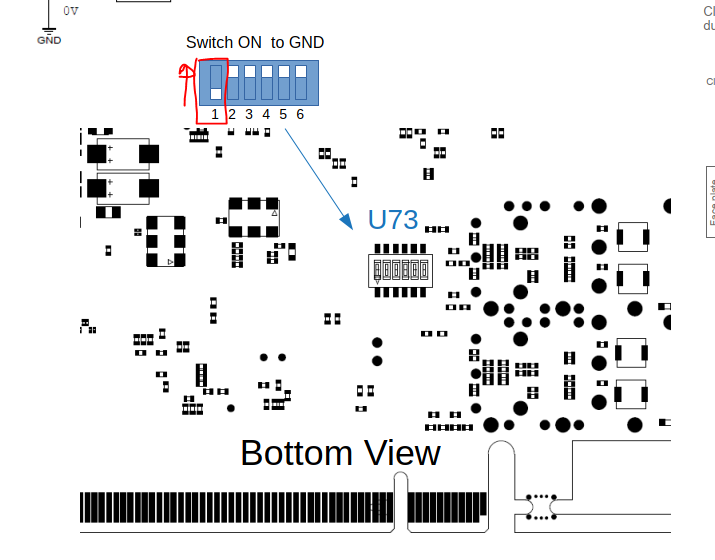
Appendix C: PCIe40v1 on-board switches
| ⇐ and ⇒ point towards and away from the PCIe connector side, respectively. |
| JTAG source | S1 | S2 |
|---|---|---|
Onboard USB blaster |
⇐ |
⇐ |
PCIe JTAG (unused) |
⇒ |
⇐ |
Faceplate JTAG |
⇐ |
⇒ |
None |
⇒ |
⇒ |
| JTAG target | S3 | S4 |
|---|---|---|
Arria10+MAX5 |
⇐ |
⇐ |
MAX5 |
⇒ |
⇐ |
Arria10 |
⇐ |
⇒ |
None |
⇒ |
⇒ |
Appendix D: PCIe40 clocks
When configuring a firmware, the following clock tree configurations are available:
-
internal
-
external
-
tfc
-
custom
Appendix E: AMC40 fiber mapping
| Number on panel | Number on MPO | FPGA pin (RX) | FPGA pin (TX) |
|---|---|---|---|
0 |
6 |
AB43 |
W41 |
1 |
8 |
Y43 |
U41 |
2 |
10 |
V43 |
R41 |
3 |
12 |
T43 |
N41 |
4 |
9 |
P43 |
L41 |
5 |
7 |
M43 |
J41 |
6 |
11 |
AM43 |
AJ41 |
7 |
2 |
AH43 |
AE41 |
8 |
3 |
AD43 |
AA41 |
9 |
5 |
AF43 |
AC41 |
10 |
1 |
AK43 |
AG41 |
11 |
4 |
AP43 |
AL41 |
| Number on panel | Number on MPO | FPGA pin (RX) | FPGA pin (TX) |
|---|---|---|---|
12 |
1 |
AP2 |
AL4 |
13 |
2 |
AM2 |
AJ4 |
14 |
12 |
AK2 |
AG4 |
15 |
11 |
AH2 |
AE4 |
16 |
9 |
AF2 |
AC4 |
17 |
7 |
AD2 |
AA4 |
18 |
5 |
K2 |
K6 |
19 |
3 |
H2 |
H6 |
20 |
4 |
F2 |
G4 |
21 |
6 |
D2 |
E4 |
22 |
10 |
B2 |
F6 |
23 |
8 |
C4 |
D6 |
| Link number | Number on MPO | FPGA pin (RX) | FPGA pin (TX) |
|---|---|---|---|
0 |
1 |
AY2 |
AU4 |
1 |
2 |
AW4 |
AT6 |
2 |
3 |
BA4 |
AV6 |
3 |
4 |
AV2 |
AR4 |
4 |
5 |
BB2 |
AY6 |
5 |
6 |
AT2 |
AN4 |
6 |
7 |
BB43 |
AY39 |
7 |
8 |
AT43 |
AN41 |
8 |
9 |
BA41 |
AV39 |
9 |
10 |
AV43 |
AR41 |
10 |
11 |
AY43 |
AU41 |
11 |
12 |
AW41 |
AT39 |
| The 10G optical link that is instantiated by default is link 1, on fibre 2. |
Appendix F: AMC40 CCPC setup
These instructions assume the following:
-
the boot server is called
lhcb-loki -
the boot server has IP address
192.168.122.1 -
the network interface connected to the CCPC LAN is
enp5s2 -
the network interface connected to the Internet is
enp3s0 -
the host name of the CCPC is
lbonccpc14 -
the MAC address of the CCPC is
00:E0:4B:43:7A:90 -
the IP address of the CCPC will be
192.168.122.14
| Of course you will have to change these values according to your specific setup. |
TYPE=Ethernet
BOOTPROTO=none
DEFROUTE=yes
...
NAME=enp5s2
DEVICE=enp5s2
ONBOOT=yes
IPADDR=192.168.122.1
PREFIX=32
GATEWAY=255.255.255.0
not authoritative;
ddns-update-style none;
deny unknown-clients;
option ip-forwarding false; # No IP forwarding
option mask-supplier false; # Don't respond to ICMP Mask req

option vendor-encapsulated-options 01:04:00:00:00:00:ff;
option vendor-class-identifier "PXEClient";

log-facility local6;
allow booting;
allow bootp;
class "pxeclients" {
  match if substring(option vendor-class-identifier, 0, 9) = "PXEClient";
  next-server 192.168.122.1;
  filename "pxelinux.0";
}

subnet 192.168.122.0 netmask 255.255.255.0 {
  option routers 192.168.122.1; # Only needed if CCPC needs internet access

  host lbonccpc14 {
    hardware ethernet 00:E0:4B:43:7A:90;
    fixed-address 192.168.122.14;
    option host-name "lbonccpc14";
  }
}
service tftp
{
        socket_type             = dgram
        protocol                = udp
        wait                    = yes
        user                    = root
        server                  = /usr/sbin/in.tftpd
        server_args             = -c -s /var/lib/tftpboot
        disable                 = no
        per_source              = 11
        cps                     = 100 2
        flags                   = IPv4
}
/var/lib/tftpboot must contain the pxelinux.0 bootloader, the kernel and initramfs images, and a file like the following (note that its name has to match the MAC address of the CCPC).
default slc_6_6

label slc_6_6
   kernel vmlinuz-2.6.39-tell40ecs
   append initrd=initramfs-2.6.39-local.img root=nfs:192.168.122.1:/scratch/exported/lbonccpc14 rw
/scratch/exported/lbonccpc14 *(rw,no_root_squash,sync,no_subtree_check)
Where /scratch/exported/lbonccpc14 is of course the path to the root filesystem for the CCPC.
...
192.168.122.14 lbonccpc14
This will be enough to correctly boot the CCPC with the given OS image. The following steps are optional and only required to give Internet access to the CCPC.
Enable IP forwading:
net.ipv4.ip_forward = 1
Ensure you’re running iptables instead of firewalld:
sudo systemctl disable firewalld
sudo yum install iptables-service && sudo systemctl enable iptables
sudo systemctl stop firewalld && sudo systemctl start iptables
Add rules to NAT from the CCPC network (enp5s2) to the WAN (enp3s0):
sudo iptables -t nat -A POSTROUTING -o enp3s0 -j MASQUERADE
sudo iptables -A FORWARD -i enp3s0 -o enp5s2 -j ACCEPT -m state --state RELATED,ESTABLISHED
sudo iptables -A FORWARD -i enp5s2 -o enp3s0 -j ACCEPT
sudo service iptables save
Once you have your CCPC able to reach the internet, it is a good idea to enable the CCPC RPM repository to automatically receive software updates. This is configured very similarly to the AMC40 and PCIe40 software, just edit or create /etc/yum.repos.d/daq40.repo according to these instructions.
Appendix G: SCA connection test
This procedure can be used as a first test to ensure that communication between the readout board and a SCA chip on the frontend can be established over a GBT link.
-
Open the GBT client from the "LHCb Framework" menu in Gedi
-
Ensure that bottom status displays "GBT Client is running" in green
-
Change the communication mechanism from "Local" to "GBT"
-
Select the SCA protocol tab
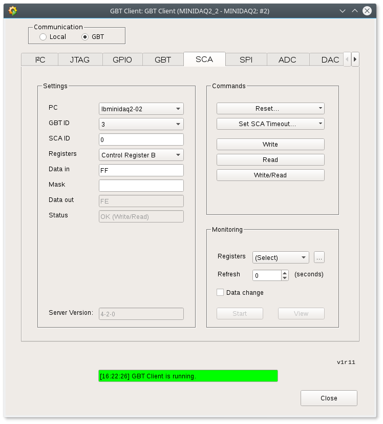
-
PC: host where the GbtServ is running
-
GBT ID: FPGA optical link connected to master GBT (e.g. fiber 8 on MPO1 → link 3, see PCIe40 fiber mapping)
-
SCA ID: select the correct SCA for your frontend (for a VLDB board, this will be 0)
-
Registers: for this test, try "Control Register B"
-
Data in:
FF -
Now click "Write/Read" and ensure the readback status is OK
-
Finally, confirm that the "Data out" field now contains
FE(since bit 0 on this register is not writeable)
| The default SCA ID set in the panel is 1, not 0. |